about
project name
Optimising Boat Tail Geometry to Minimise Rocket Drag
Optimising Boat Tail Geometry to Minimise Rocket Drag
date
Jul. 2024 - Nov. 2024
overview
This is a qualitative study on the optimal boat tail shape and length that minimizes the drag of a rocket. The study mainly compares the drag performance of ogive and conical boattails, alongside the effect of their length on the rocket's drag force.
background
This study was initiated to inform the boat tail design of ARES' Project Lemaire, a rocket intended to compete in the 30,000 ft category of the 2025 Spaceport America Cup.
A boat tail is a tapering section added to the end of a rocket. It reduces the size of the rocket's wake, which in turn lowers the base drag acting behind the rocket.
This base drag arises from the region of low pressure air left in the rocket's wake, which creates a suction-like effect that 'pulls' rocket back while it moves forwards.
In this study, the drag performance between ogive and conical boat tails was qualitatively investigated over the subsonic, transonic, and supersonic velocities that Project Lemaire would fly at. The relationship between boat tail length and rocket drag was also investigated to see whether longer or shorter boat tails generated less drag.

The wake-reducing effect of boat tails.
Image credit: Estes Rocketry
background
This study was initiated to inform the boat tail design of ARES' Project Lemaire, a rocket intended to compete in the 30,000 ft category of the 2025 Spaceport America Cup.
A boat tail is a tapering section added to the end of a rocket. It reduces the size of the rocket's wake, which in turn lowers the base drag acting behind the rocket.
This base drag arises from the region of low pressure air left in the rocket's wake, which creates a suction-like effect that 'pulls' rocket back while it moves forwards.
In this study, the drag performance between ogive and conical boat tails was qualitatively investigated over the subsonic, transonic, and supersonic velocities that Project Lemaire would fly at. The relationship between boat tail length and rocket drag was also investigated to see whether longer or shorter boat tails generated less drag.
The wake-reducing effect of boat tails.
Image credit: Estes Rocketry
methodology
The drag performance of different boat tail geometries was compared via CFD simulations performed on ANSYS Fluent. The boat tail length and shape investigations were both conducted with a similar methodology, which is outlined below:
Modelling the Lemaire rocket for simulations with CAD
Using OnShape, 2 CAD models of the rocket were generated for the boat tail shape investigation: one model had a conical boat tail whilst the other featured an ogive boat tail. For the boat tail length investigation, 6 CAD models of the rocket were created, each featuring conical boat tails that ranged between 125 mm to 250 mm long.

The CAD models used in the boat tail shape investigation. Similar models were created for the boat tail length investigation.
The relevant enclosures, bodies of influence, and surfaces to be simulated in ANSYS Fluent were created with SpaceClaim
Given the symmetrical shape of a rocket, the CAD models were quartered to save on computational cost and time. Provided that the simulation was correctly setup, the drag force for the whole rocket body could be reasonably estimated by multiplying the quartered models' drag forces by 4.

The quartered rocket model and enclosure used in the boat tail shape/length simulations.
Mesh independence studies
Mesh independent studies were conducted to find the optimal mesh that balanced the accuracy of the drag force calculated for the quartered rocket models with computational cost/time. The optimal mesh was identified by testing various mesh cell counts and identifying the cell count at which drag force began to converge.
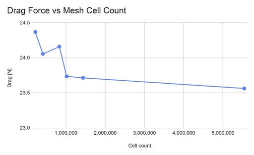
A plot of calculated drag force vs mesh cell count, obtained from the mesh independence study performed for the boat tail shape investigation.
Batch simulations ANSYS Fluent simulations
Once the suitable mesh was selected, CFD simulations were performed on the quartered rocket models to calculate their drag force at velocities representing the subsonic, transonic, and supersonic flight regimes that Lemaire would encounter. These velocities ranged between Mach 0.3 and 1.6.
The CFD simulations were submitted to the University of Melbourne's High Performance Computing (HPC) system so that they could be completed in a time-efficient manner and without constant supervision.
key results
For the boat tail shape investigation, the conical boat tail was consistently found to produce less drag than its ogive counterpart across the subsonic, transonic, and supersonic velocities.
The conical boat tail's lower drag was influenced by its sloping profile, which redirected the flow earlier than the ogive boat tail’s curved profile and thereby enabled a tighter, narrower wake (i.e. less base drag).
Interestingly, the ogive boat tail featured a greater amount of vortex shedding compared to the conical boat tail model. From an energy perspective, the vortices are generated from the rocket's kinetic energy and are a mechanism through which the rocket loses kinetic energy during flight.
Hence, the conical boat tail was concluded to generate less drag than the ogive boat tail, given its smaller wake and reduced vortex shedding compared to the latter.

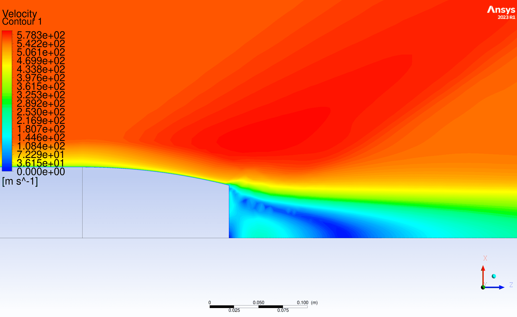
Comparison of velocity contours for the ogive (top) and conical (bottom) boat tails at Mach 1.6. Note the smaller wake and reduced vortex shedding in the conical boat tail model.
For the boat tail length investigation, the drag force was observed to decrease with increasing boat tail length. The longest tested boat tail length of 250 mm was consequently found to offer the best performance across the subsonic, transonic, and supersonic velocities encountered by Lemaire.
In particular, although the 250 mm boat tail generated between 0.36 N–1.6 N of additional drag compared to the 125 mm boat tail (the shortest tested length) at Mach 0.3–0.6, it also produced up to 15.6 N less drag compared to the 125 mm version at velocities beyond Mach 0.6.
Thus, the 250 mm boat tail was the optimal boat tail length as it produced noticeably less drag at supersonic velocities than its shorter counterparts while also performing relatively similarly at subsonic velocities.

Drag forces calculated for boat tail lengths ranging between 125 mm and 250 mm at Mach 0.3, 0.6, 1.0, and 1.5.
project name
Optimising Boat Tail Geometry to Minimise Rocket Drag
date
Jul. 2024 - Nov. 2024
overview
This is a qualitative study on the optimal boat tail shape and length that minimizes the drag of a rocket. The study mainly compares the drag performance of ogive and conical boattails, alongside the effect of their length on the rocket's drag force.
background
This study was initiated to inform the boat tail design of ARES' Project Lemaire, a rocket intended to compete in the 30,000 ft category of the 2025 Spaceport America Cup.
A boat tail is a tapering section added to the end of a rocket. It reduces the size of the rocket's wake, which in turn lowers the base drag acting behind the rocket.
This base drag arises from the region of low pressure air left in the rocket's wake, which creates a suction-like effect that 'pulls' rocket back while it moves forwards.
In this study, the drag performance between ogive and conical boat tails was qualitatively investigated over the subsonic, transonic, and supersonic velocities that Project Lemaire would fly at. The relationship between boat tail length and rocket drag was also investigated to see whether longer or shorter boat tails generated less drag.
The wake-reducing effect of boat tails.
Image credit: Estes Rocketry
methodology
The drag performance of different boat tail geometries was compared via CFD simulations performed on ANSYS Fluent. The boat tail length and shape investigations were both conducted with a similar methodology, which is outlined below:
Modelling the Lemaire rocket for simulations with CAD
Using OnShape, 2 CAD models of the rocket were generated for the boat tail shape investigation: one model had a conical boat tail whilst the other featured an ogive boat tail. For the boat tail length investigation, 6 CAD models of the rocket were created, each featuring conical boat tails that ranged between 125 mm to 250 mm long.
The CAD models used in the boat tail shape investigation. Similar models were created for the boat tail length investigation.
The relevant enclosures, bodies of influence, and surfaces to be simulated in ANSYS Fluent were created with SpaceClaim
Given the symmetrical shape of a rocket, the CAD models were quartered to save on computational cost and time. Provided that the simulation was correctly setup, the drag force for the whole rocket body could be reasonably estimated by multiplying the quartered models' drag forces by 4.
The quartered rocket model and enclosure used in the boat tail shape/length simulations.
Mesh independence studies
Mesh independent studies were conducted to find the optimal mesh that balanced the accuracy of the drag force calculated for the quartered rocket models with computational cost/time. The optimal mesh was identified by testing various mesh cell counts and identifying the cell count at which drag force began to converge.
A plot of calculated drag force vs mesh cell count, obtained from the mesh independence study performed for the boat tail shape investigation.
Batch simulations ANSYS Fluent simulations
Once the suitable mesh was selected, CFD simulations were performed on the quartered rocket models to calculate their drag force at velocities representing the subsonic, transonic, and supersonic flight regimes that Lemaire would encounter. These velocities ranged between Mach 0.3 and 1.6.
The CFD simulations were submitted to the University of Melbourne's High Performance Computing (HPC) system so that they could be completed in a time-efficient manner and without constant supervision.
key results
For the boat tail shape investigation, the conical boat tail was consistently found to produce less drag than its ogive counterpart across the subsonic, transonic, and supersonic velocities.
The conical boat tail's lower drag was influenced by its sloping profile, which redirected the flow earlier than the ogive boat tail’s curved profile and thereby enabled a tighter, narrower wake (i.e. less base drag).
Interestingly, the ogive boat tail featured a greater amount of vortex shedding compared to the conical boat tail model. From an energy perspective, the vortices are generated from the rocket's kinetic energy and are a mechanism through which the rocket loses kinetic energy during flight.
Hence, the conical boat tail was concluded to generate less drag than the ogive boat tail, given its smaller wake and reduced vortex shedding compared to the latter.
Comparison of velocity contours for the ogive (top) and conical (bottom) boat tails at Mach 1.6. Note the smaller wake and reduced vortex shedding in the conical boat tail model.
For the boat tail length investigation, the drag force was observed to decrease with increasing boat tail length. The longest tested boat tail length of 250 mm was consequently found to offer the best performance across the subsonic, transonic, and supersonic velocities encountered by Lemaire.
In particular, although the 250 mm boat tail generated between 0.36 N–1.6 N of additional drag compared to the 125 mm boat tail (the shortest tested length) at Mach 0.3–0.6, it also produced up to 15.6 N less drag compared to the 125 mm version at velocities beyond Mach 0.6.
Thus, the 250 mm boat tail was the optimal boat tail length as it produced noticeably less drag at supersonic velocities than its shorter counterparts while also performing relatively similarly at subsonic velocities.
Drag forces calculated for boat tail lengths ranging between 125 mm and 250 mm at Mach 0.3, 0.6, 1.0, and 1.5.