about
click/drag/scroll the model to explore
click the dots below to view other models
tap/drag/pinch the model to explore
tap the dots beside to view other models
project name
L1 Rocket
date
Oct. 2023
overview
The L1 rocket was my first attempt in building a high-powered model rocket for the L1 (Level 1) certification from the Tripoli Rocketry Association. Although the rocket's flight was a success, I didn't get certified as I couldn't recover the rocket in time for inspection.
background
Between August and October 2023, I designed and launched a rocket in the attempt of obtaining my L1 (Level 1) certification from the Tripoli Rocketry Association (TRA).
The L1 certification is part of the TRA certification process that allows rocketry enthusiasts to use rocket motors that are larger and more powerful (as well as dangerous!) than those typically found in model rocketry kits.
Rocket motors are classed by the total impulse (the effect of the motor's thrust acting over time) they deliver, which fall into ranges represented by letters (see this Wikipedia page for more).
Obtaining the L1 certification would allow me to buy and use H/I impulse class rocket motors, which can deliver impulses of anywhere between 160 and 640 Newton-seconds.
the challenge
The TRA lists an extensive number of rules and conditions on building and flying an L1 certification rocket. In summary, my main objective was to build a rocket that would launch with an H/I impulse class rocket motor, deploy a parachute after reaching its peak altitude, and be recovered in a flightworthy condition.
Hence, I identified the following challenges pertaining to the rocket's design:
The rocket must incorporate a parachute recovery system that deploys during its descent.
The rocket must be robust enough to resist the forces from the motor burning sequence during launch, ejection charges during parachute deployment, and ground impacts when landing.
The rocket must remain flightworthy after launch and recovery, i.e. it should not sustain damage that prevents it from being immediately flown again with a new motor.
The rocket must be designed with enough stability to ensure that it does not wobble/veer off during flight. Stability is a key consideration in model rocketry, and is determined by how the rocket's center of gravity and center of pressure are positioned relative to one another. Ideally, a rocket's center of gravity should lie ahead of its center of pressure by 1-2 calibers (1 caliber = the rocket's diameter) for it to maintain a straight, upwards flight path.
key design choices
Durability, repairability, and versatility were key considerations that influenced the L1 rocket's design.
The features of the L1 rocket where key design choices were made are shown below:


The rocket was designed to fly on various H/I class rocket motors (Aerotech H100, H195, or I205) with a good degree of stability despite their different weights and sizes.
This allowed me to fly the rocket with a wider selection of rocket motors, which proved especially helpful at the launch site since there were a limited number of H/I class rocket motors for L1 flyers to use.

The rocket's nose cone was designed to be screwed onto its upper body tube. This allowed the nose cone to be replaced in the event of damage, where a damaged nose cone could be simply unscrewed and swapped out for its replacement.
The fins have a clipped geometry that reduces their likelihood of chipping/cracking from ground impacts. The fins were also constructed from 6mm plywood instead of 3mm plywood for additional durability.
The fins were vertically offset from the end of rocket to reduce direct impacts with ground during landing.
The rocket was designed to fly on various H/I class rocket motors (Aerotech H100, H195, or I205) with a good degree of stability despite their different weights and sizes.
This allowed me to fly the rocket with a wider selection of rocket motors, which proved especially helpful at the launch site since there were a limited number of H/I class rocket motors for L1 flyers to use.
The rocket's nose cone was designed to be screwed onto its upper body tube. This allowed the nose cone to be replaced in the event of damage, where a damaged nose cone could be simply unscrewed and swapped out for its replacement.
The fins have a clipped geometry that reduces their likelihood of chipping/cracking from ground impacts. The fins were also constructed from 6mm plywood instead of 3mm plywood for additional durability.
The fins were vertically offset from the end of rocket to reduce direct impacts with ground during landing.
The rocket was designed to fly on various H/I class rocket motors (Aerotech H100, H195, or I205) with a good degree of stability despite their different weights and sizes. This allowed me to fly the rocket with a wider selection of rocket motors, which proved especially helpful at the launch site since there were a limited number of H/I class rocket motors for L1 flyers to use.
The rocket's nose cone was designed to be screwed onto its upper body tube. This allowed the nose cone to be replaced in the event of damage, where a damaged nose cone could be simply unscrewed and swapped out for its replacement.
The fins have a clipped geometry that reduces their likelihood of chipping/cracking from ground impacts. The fins were also constructed from 6mm plywood instead of 3mm plywood for additional durability.
The fins were vertically offset from the end of rocket to reduce direct impacts with ground during landing.
manufacturing
The rocket was built using 60mm cardboard tubes, plywood, PVC piping, PLA, and epoxy. Building this rocket allowed me to refine and learn new manufacturing skills, such as working with 3D printers, epoxy, and power tools.
Below are the notable moments from the rocket's manufacturing process:
The left photo shows the rocket's motor tube (a 40mm PVC pipe) being test-fitted with its centering rings inside the lower body tube (a 60mm cardboard tube). I found that the parachute eyebolt was too close to the rocket's inner walls for the parachute cord to be threaded through by hand.
To resolve this, I designed a bulkhead (pictured right) that allowed the eyebolt to hang inside the motor tube without obstructing the tube opening, which was crucial for channeling the hot gases from the motor's ejection charge during the parachute's deployment.
This was the motor tube with its centering rings and eyebolt bulkhead epoxied on. The PVC pipe was sanded down to remove its smooth outer finish so that the epoxy could effectively bond the centering rings to the motor tube.

The rocket's fins were fitted into cutouts made along the rocket's lower body tube and epoxied onto the motor tube.
To ensure that the fins were equally spaced apart and perpendicular to the body tube as the epoxy cured, I created a jig with cutouts that maintained the fins' orientation during the curing process (shown left).
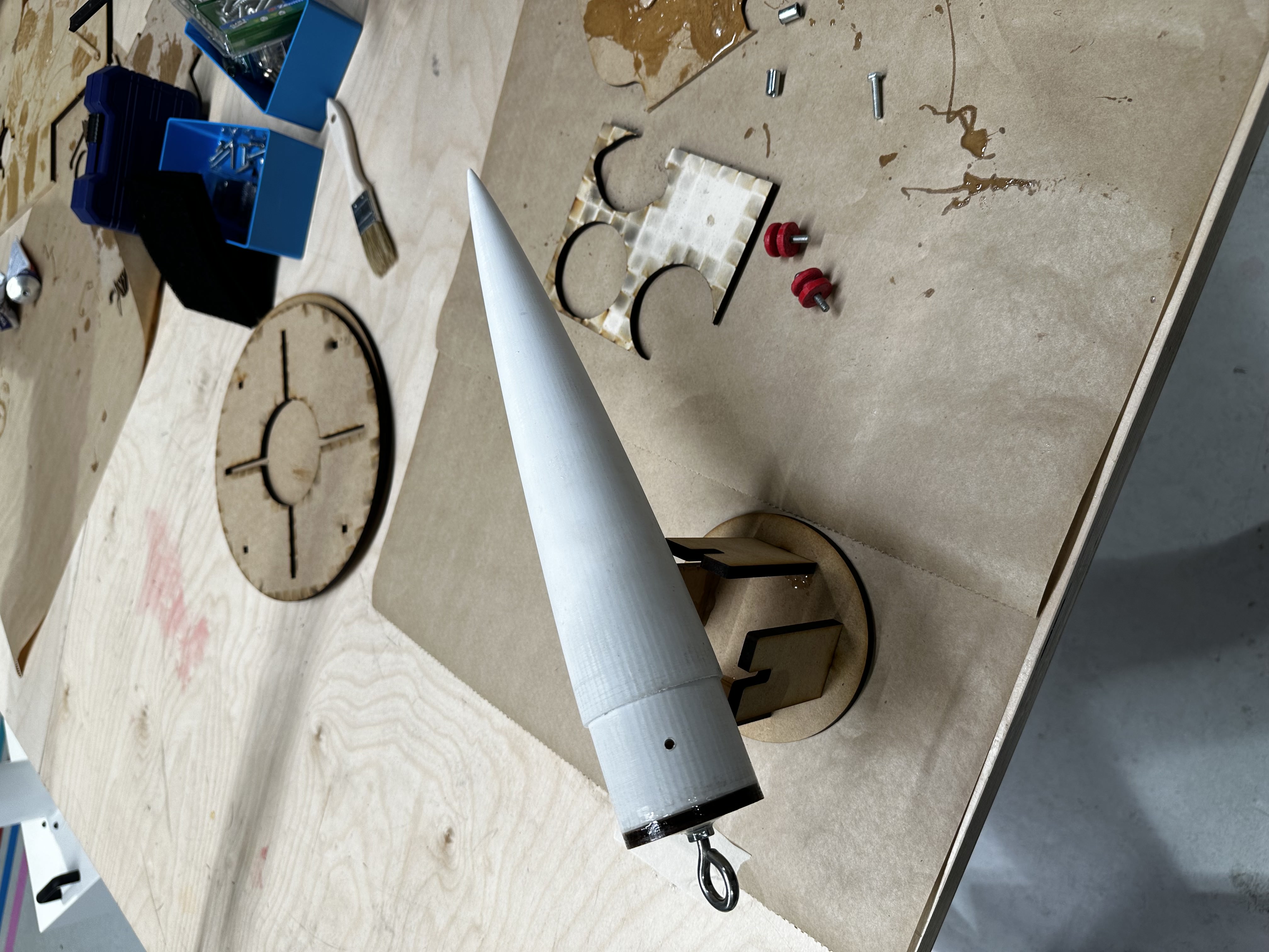
The nose cone was 3D printed with PLA, using a greater number of shells and infill density for additional durability and impact resistance.
The nose cone was sanded to a smooth finish and drilled to create its screw holes. The plywood bulkhead and eye bolt were also epoxied to the base of the nose cone.
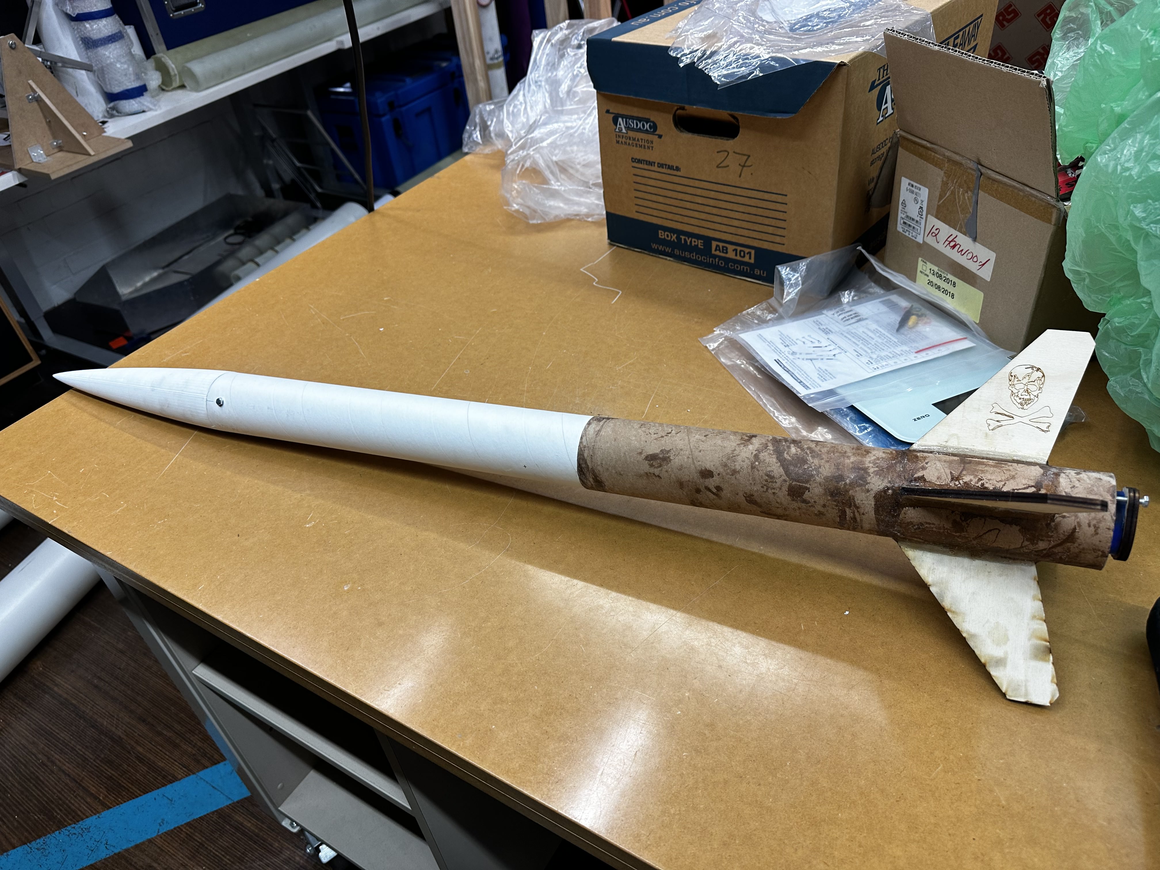

The assembled rocket before painting.
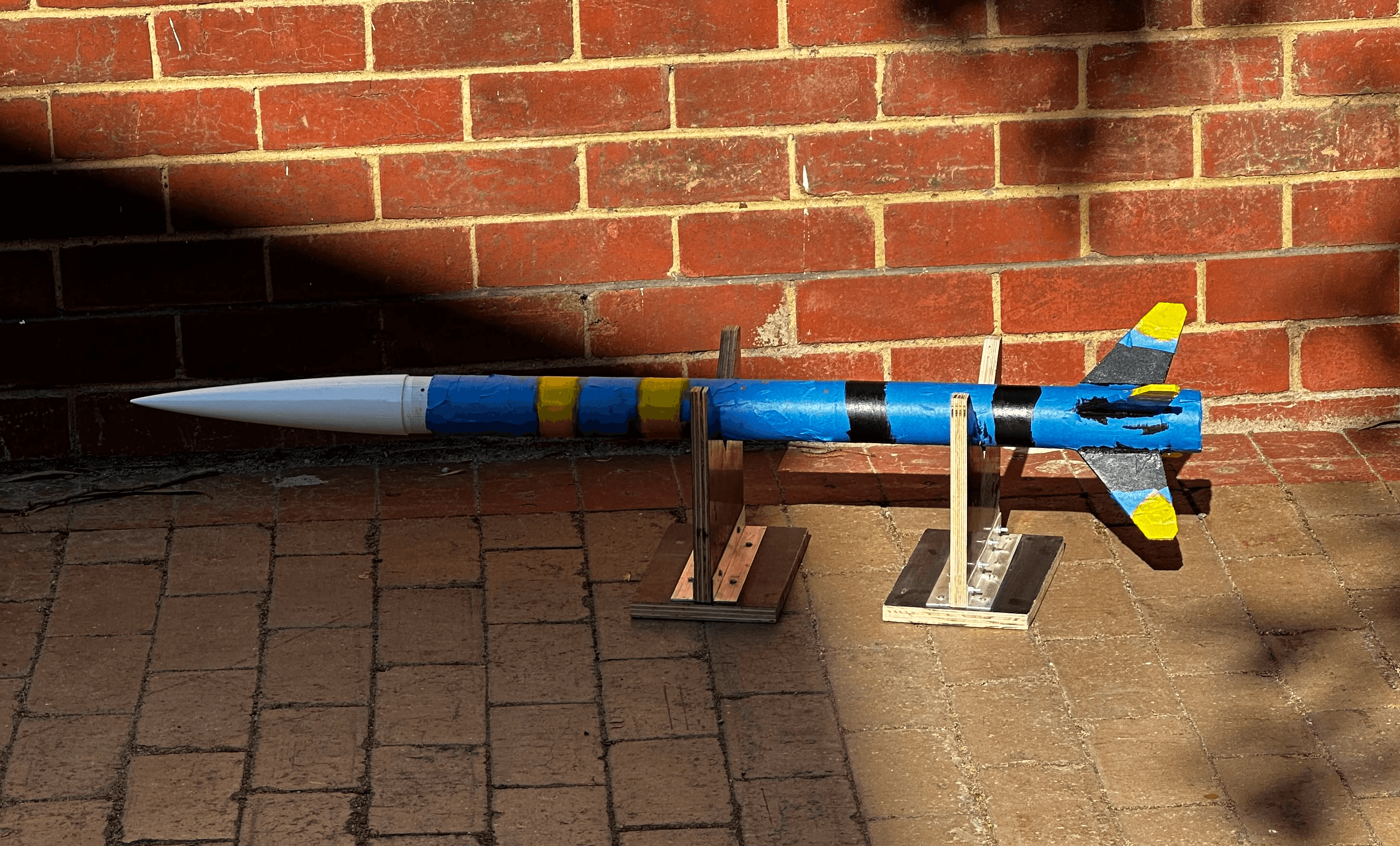

The rocket was both hand and spray-painted; the nose cone and body tubes were spray painted, while the fins, stripes, and detailing where painted by hand. The nose cone was also given a glossy clear varnish to protect its white finish from water damage and scratches.
The rocket was both hand and spray-painted; the nose cone and body tubes were spray painted, while the fins, stripes, and detailing where painted by hand.
The nose cone was also given a glossy clear varnish to protect its white finish from water damage and scratches.

The final rocket measured 110 cm long and weighed 0.8 kg without a motor. Its stability margin ranged between 1.65 to 1.96 calibers (which is quite stable!), depending on whether it was fitted with a H100, H195, or I205 motor.
The final rocket measured 110 cm long and weighed 0.8 kg without a motor.
Its stability margin ranged between 1.65 to 1.96 calibers (which is quite stable!), depending on whether it was fitted with a H100, H195, or I205 motor.
launch day
On Oct 1, I travelled the Victorian Rocketry Association's (VRA) Serpentine launch site for my L1 rocket's certification flight. After preparing my rocket's parachute and getting the rocket inspected by the VRA officer, I was allowed to set my rocket on the launch pad and wire its motor to the remote detonator. Below are some photos and videos from the launch:
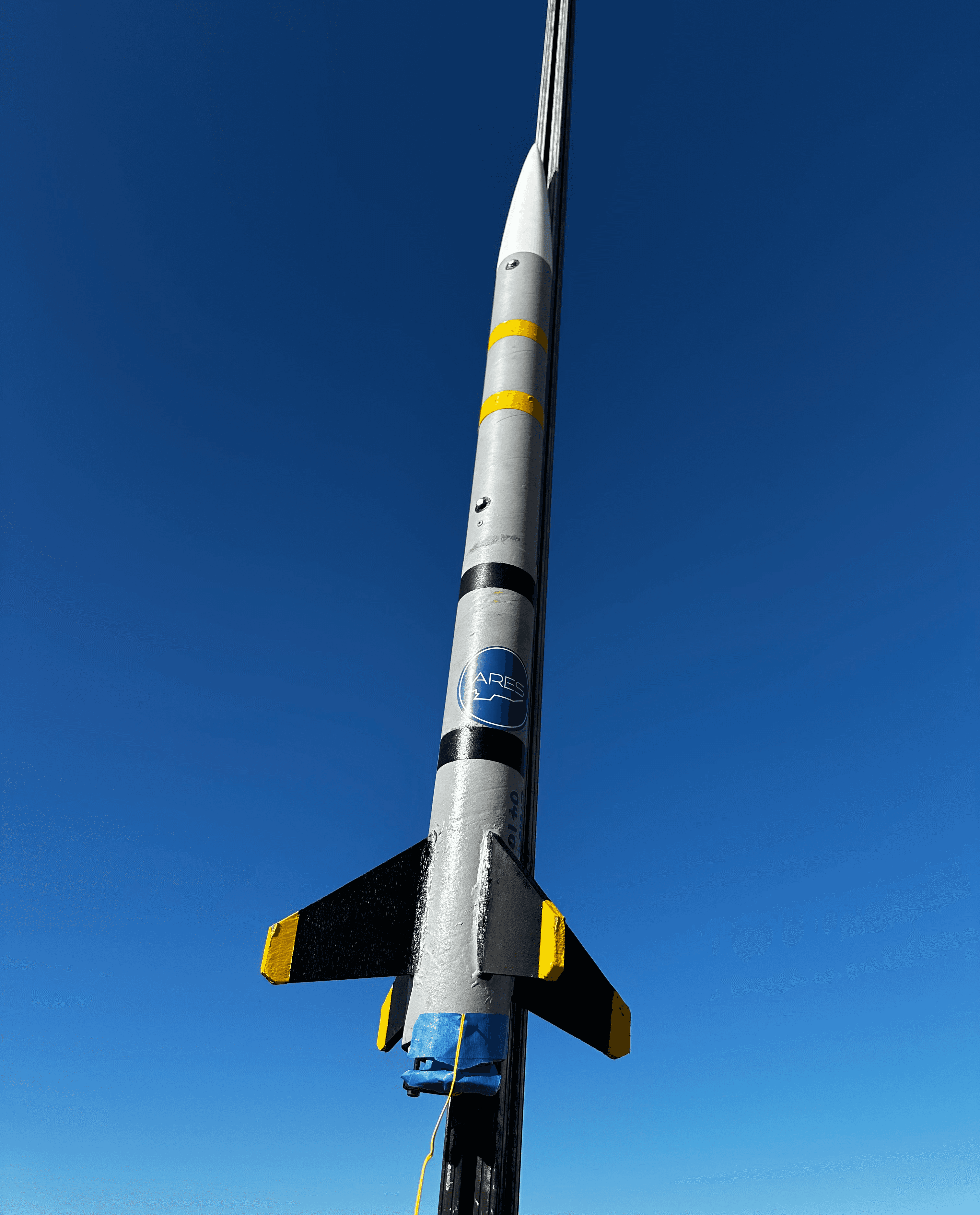
The L1 rocket on the launch rail at Serpentine.
The final rocket measured 110 cm long and weighed 0.8 kg without a motor.
Its stability margin ranged between 1.65 to 1.96 calibers (which is quite stable!), depending on whether it was fitted with a H100, H195, or I205 motor.
Footage of the rocket launch.
post-flight & learnings
Unfortunately, I failed to recover the L1 rocket despite its successful launch and recovery. This was mainly due to the launch site being located over a maturing crop field, in which the crop plants were almost a meter tall and made it virtually impossible to spot the rocket from a distance. Since the rocket did not carry any tracking devices and had drifted to a considerable distance from the launch site, I spent the entire afternoon searching for a rocket-shaped 'needle' amidst the 'haystack' of crop plants!
Since I failed to find the rocket by the end of the launch day, I could not obtain my L1 certification as I did not present my rocket for the mandatory post-flight inspection. This was a greatly disappointing outcome for me, especially since I spent over a week continously building the rocket.
Excluding my failure to recover the rocket, my first L1 rocket was successful as it launched and deployed its parachute without any issues. However, there is definitely room for improvement regarding the rocket's design and manufacturing process, which I have listed below:
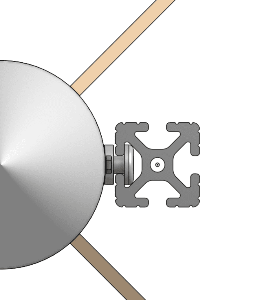
The rocket's rail buttons (plastic guides that allowed the rocket to slide along the launch rail) were too short to run smoothly along the launch rail (see right). This forced me to sand the rail buttons down at the launch site until they could travel smoothly along the rail.
The rocket's rail buttons (plastic guides that allowed the rocket to slide along the launch rail) were too short to run smoothly along the launch rail (see right).
This forced me to sand the rail buttons down at the launch site until they could travel smoothly along the rail.
The rocket's 60 mm diameter made it cumbersome to integrate the parachute recovery system. For instance, a small eye bolt could not be mounted beside the motor tube (see right) as it was too close to the rocket's inner wall (see right) for the parachute cord to be tied on.
The rocket's 60 mm diameter made it cumbersome to integrate the parachute recovery system.
For instance, a small eye bolt could not be mounted beside the motor tube (see right) as it was too close to the rocket's inner wall (see right) for the parachute cord to be tied on.
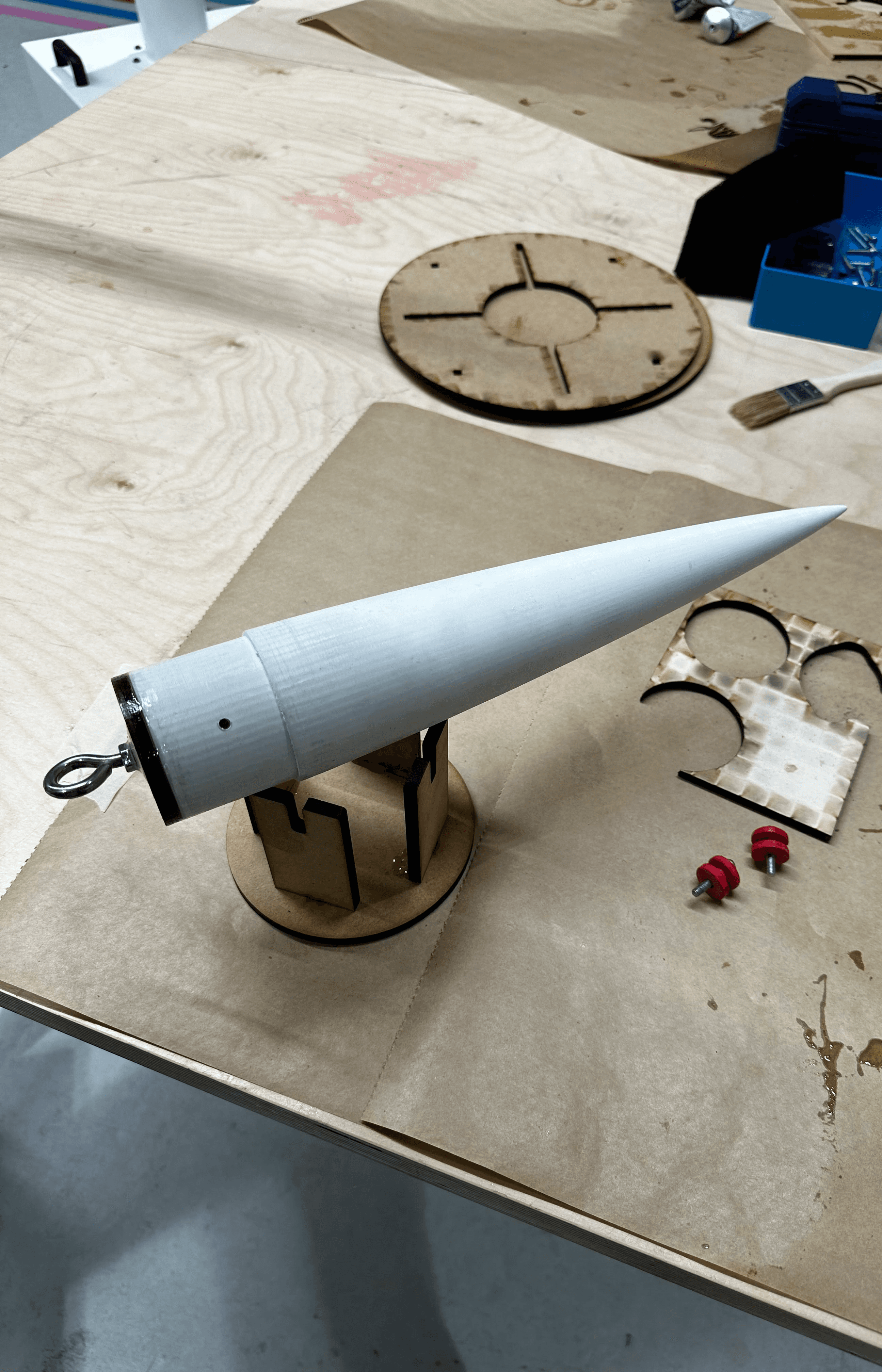
Certain components could have been manufactured faster if their designs were simplified. For instance, the nose cone featured a plywood bulkhead that was fitted with an eye bolt to serve as a parachute attachment point. However, the bulkhead and eye bolt were not entirely necessary and could've been removed from the manufacturing process by 3D printing the nose cone with an internal loop/bar for the parachute attachment point.
Certain components could have been manufactured faster if their designs were simplified. For instance, the nose cone featured a plywood bulkhead that was fitted with an eye bolt to serve as a parachute attachment point.
However, the bulkhead and eye bolt were not entirely necessary and could've been removed from the manufacturing process by 3D printing the nose cone with an internal loop/bar for the parachute attachment point.
Despite the aforementioned setbacks, I am determined to build another rocket and obtain the L1 certification, especially given my newly-acquired experience in designing and building a high-powered model rocket. In fact, I have already begun designing my next L1 rocket and will aim to build it sometime in the later half of 2024, during which I will be regularly updating this portfolio with my progress on assembling my next L1 rocket.
tap/drag/pinch the model to explore
tap the dots beside to view other models
project name
L1 Rocket
date
Oct. 2023
overview
The L1 rocket was my first attempt in building a high-powered model rocket for the L1 (Level 1) certification from the Tripoli Rocketry Association. Although the rocket's flight was a success, I didn't get certified as I couldn't recover the rocket in time for inspection.
background
Between August and October 2023, I designed and launched a rocket in the attempt of obtaining my L1 (Level 1) certification from the Tripoli Rocketry Association (TRA).
The L1 certification is part of the TRA certification process that allows rocketry enthusiasts to use rocket motors that are larger and more powerful (as well as dangerous!) than those typically found in model rocketry kits.
Rocket motors are classed by the total impulse (the effect of the motor's thrust acting over time) they deliver, which fall into ranges represented by letters (see this Wikipedia page for more).
Obtaining the L1 certification would allow me to buy and use H/I impulse class rocket motors, which can deliver impulses of anywhere between 160 and 640 Newton-seconds.

A H195 (H-class) rocket motor
Image credit: Apogee Components, Inc.
the challenge
The TRA lists an extensive number of rules and conditions on building and flying an L1 certification rocket. In summary, my main objective was to build a rocket that would launch with an H/I impulse class rocket motor, deploy a parachute after reaching its peak altitude, and be recovered in a flightworthy condition.
Hence, I identified the following challenges pertaining to the rocket's design:
The rocket must incorporate a parachute recovery system that deploys during its descent.
The rocket must be robust enough to resist the forces from the motor burning sequence during launch, ejection charges during parachute deployment, and ground impacts when landing.
The rocket must remain flightworthy after launch and recovery, i.e. it should not sustain damage that prevents it from being immediately flown again with a new motor.
The rocket must be designed with enough stability to ensure that it does not wobble/veer off during flight. Stability is a key consideration in model rocketry, and is determined by how the rocket's center of gravity and center of pressure are positioned relative to one another. Ideally, a rocket's center of gravity should lie ahead of its center of pressure by 1-2 calibers (1 caliber = the rocket's diameter) for it to maintain a straight, upwards flight path.
key design choices
Durability, repairability, and versatility were key considerations that influenced the L1 rocket's design.
The features of the L1 rocket where key design choices were made are shown below:
The rocket was designed to fly on various H/I class rocket motors (Aerotech H100, H195, or I205) with a good degree of stability despite their different weights and sizes.
This allowed me to fly the rocket with a wider selection of rocket motors, which proved especially helpful at the launch site since there were a limited number of H/I class rocket motors for L1 flyers to use.
The rocket's nose cone was designed to be screwed onto its upper body tube. This allowed the nose cone to be replaced in the event of damage, where a damaged nose cone could be simply unscrewed and swapped out for its replacement.
The fins have a clipped geometry that reduces their likelihood of chipping/cracking from ground impacts. The fins were also constructed from 6mm plywood instead of 3mm plywood for additional durability.
The fins were vertically offset from the end of rocket to reduce direct impacts with ground during landing.
The rocket was designed to fly on various H/I class rocket motors (Aerotech H100, H195, or I205) with a good degree of stability despite their different weights and sizes. This allowed me to fly the rocket with a wider selection of rocket motors, which proved especially helpful at the launch site since there were a limited number of H/I class rocket motors for L1 flyers to use.
The rocket's nose cone was designed to be screwed onto its upper body tube. This allowed the nose cone to be replaced in the event of damage, where a damaged nose cone could be simply unscrewed and swapped out for its replacement.
The fins have a clipped geometry that reduces their likelihood of chipping/cracking from ground impacts. The fins were also constructed from 6mm plywood instead of 3mm plywood for additional durability.
The fins were vertically offset from the end of rocket to reduce direct impacts with ground during landing.
manufacturing
The rocket was built using 60mm cardboard tubes, plywood, PVC piping, PLA, and epoxy. Building this rocket allowed me to refine and learn new manufacturing skills, such as working with 3D printers, epoxy, and power tools.
Below are the notable moments from the rocket's manufacturing process:
The left photo shows the rocket's motor tube (a 40mm PVC pipe) being test-fitted with its centering rings inside the lower body tube (a 60mm cardboard tube). I found that the parachute eyebolt was too close to the rocket's inner walls for the parachute cord to be threaded through by hand.
To resolve this, I designed a bulkhead (pictured right) that allowed the eyebolt to hang inside the motor tube without obstructing the tube opening, which was crucial for channeling the hot gases from the motor's ejection charge during the parachute's deployment.
This was the motor tube with its centering rings and eyebolt bulkhead epoxied on. The PVC pipe was sanded down to remove its smooth outer finish so that the epoxy could effectively bond the centering rings to the motor tube.
The rocket's fins were fitted into cutouts made along the rocket's lower body tube and epoxied onto the motor tube.
To ensure that the fins were equally spaced apart and perpendicular to the body tube as the epoxy cured, I created a jig with cutouts that maintained the fins' orientation during the curing process (shown left).
The nose cone was 3D printed with PLA, using a greater number of shells and infill density for additional durability and impact resistance.
The nose cone was sanded to a smooth finish and drilled to create its screw holes. The plywood bulkhead and eye bolt were also epoxied to the base of the nose cone.
The assembled rocket before painting.
The rocket was both hand and spray-painted; the nose cone and body tubes were spray painted, while the fins, stripes, and detailing where painted by hand.
The nose cone was also given a glossy clear varnish to protect its white finish from water damage and scratches.
The final rocket measured 110 cm long and weighed 0.8 kg without a motor.
Its stability margin ranged between 1.65 to 1.96 calibers (which is quite stable!), depending on whether it was fitted with a H100, H195, or I205 motor.
launch day
On Oct 1, I travelled the Victorian Rocketry Association's (VRA) Serpentine launch site for my L1 rocket's certification flight. After preparing my rocket's parachute and getting the rocket inspected by the VRA officer, I was allowed to set my rocket on the launch pad and wire its motor to the remote detonator. Below are some photos and videos from the launch:
The final rocket measured 110 cm long and weighed 0.8 kg without a motor.
Its stability margin ranged between 1.65 to 1.96 calibers (which is quite stable!), depending on whether it was fitted with a H100, H195, or I205 motor.
Footage of the rocket launch.
post-flight & learnings
Unfortunately, I failed to recover the L1 rocket despite its successful launch and recovery. This was mainly due to the launch site being located over a maturing crop field, in which the crop plants were almost a meter tall and made it virtually impossible to spot the rocket from a distance. Since the rocket did not carry any tracking devices and had drifted to a considerable distance from the launch site, I spent the entire afternoon searching for a rocket-shaped 'needle' amidst the 'haystack' of crop plants!
Since I failed to find the rocket by the end of the launch day, I could not obtain my L1 certification as I did not present my rocket for the mandatory post-flight inspection. This was a greatly disappointing outcome for me, especially since I spent over a week continously building the rocket.
Excluding my failure to recover the rocket, my first L1 rocket was successful as it launched and deployed its parachute without any issues. However, there is definitely room for improvement regarding the rocket's design and manufacturing process, which I have listed below:
The rocket's rail buttons (plastic guides that allowed the rocket to slide along the launch rail) were too short to run smoothly along the launch rail (see right).
This forced me to sand the rail buttons down at the launch site until they could travel smoothly along the rail.
The rocket's 60 mm diameter made it cumbersome to integrate the parachute recovery system.
For instance, a small eye bolt could not be mounted beside the motor tube (see right) as it was too close to the rocket's inner wall (see right) for the parachute cord to be tied on.

Certain components could have been manufactured faster if their designs were simplified. For instance, the nose cone featured a plywood bulkhead that was fitted with an eye bolt to serve as a parachute attachment point.
However, the bulkhead and eye bolt were not entirely necessary and could've been removed from the manufacturing process by 3D printing the nose cone with an internal loop/bar for the parachute attachment point.
Despite the aforementioned setbacks, I am determined to build another rocket and obtain the L1 certification, especially given my newly-acquired experience in designing and building a high-powered model rocket. In fact, I have already begun designing my next L1 rocket and will aim to build it sometime in the later half of 2024, during which I will be regularly updating this portfolio with my progress on assembling my next L1 rocket.