about
click/drag/scroll the model to explore
click the dots below to view other models
tap/drag/pinch the model to explore
tap the dots beside to view other models
project name
Payload Retention
date
Aug. 2023 - Jun. 2024
overview
As a student engineer in the University of Melbourne's rocketry team (ARES), I designed and manufactured the payload retention subsystem for Project Florence, a rocket built by the team to compete in the 2024 Spaceport America Cup.
background
As a student engineer in the University of Melbourne's rocketry team (ARES), I was responsible for designing and manufacturing the payload retention subsystem for Project Florence (pictured right), a rocket designed by the team to compete in the 30,000 ft category of the 2024 Spaceport America Cup.
The payload retention subsystem is essentially a protective frame/housing in which the rocket's payload (i.e. the rocket's cargo) stored. It ensures that the payload does not wobble, vibrate, or become dislodged throughout the rocket's entire flight, especially during high acceleration events (launch, ascent, etc.)
As a student engineer in the University of Melbourne's rocketry club (ARES), I was responsible for designing and manufacturing the payload retention subsystem for Florence (pictured right), a rocket designed to compete in the 30,000 ft category of the 2024 Spaceport America Cup.
The payload retention subsystem is essentially a protective frame/housing in which the rocket's payload (i.e. the rocket's cargo) stored.
It ensures that the payload does not wobble, vibrate, or become dislodged throughout the rocket's entire flight, especially during high acceleration events (launch, ascent, etc.)

Project Florence, 09/06/2024
design requirements
Designing the payload retention during Project Florence involved satisfying performance requirements and constraints stipulated by the rocket's design as well as the Spaceport America Cup rules. The payload retention's design requirements included the following:
The system should accommodate a payload with the dimensions of a 3U CubeSat (100mm x 100mm x 300mm).
The system must safely retain the payload in the rocket throughout the entire flight, especially during high acceleration conditions such as the launch and motor-burning flight sequences. It must withstand the expected maximum load (902N) with a safety factor of 1.5-2 (i.e. be robust enough to support 1.5-2 times the expected maximum load).
The system should allow for convenient payload insertion/removal and be easily integrated within the rocket without interfering with neighboring subsystems.
The system's mass does not exceed 400g.
design iterations
Various designs were investigated for the payload retention subsystem, in which retention methods involving spacers, tensioning rods, cages, and removable walls were each investigated and evaluated. Here are some of the solutions that were explored:
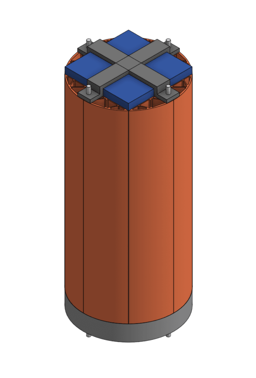
Design 1: This design secures the payload (in blue) with an aluminum retention plate, brackets, and tensioning rods.
It also features 3D printed PLA spacers (in orange) that fill the space between the payload and inner walls of the rocket's body tube, which provide protection from side impacts as well as limit horizontal vibrations.
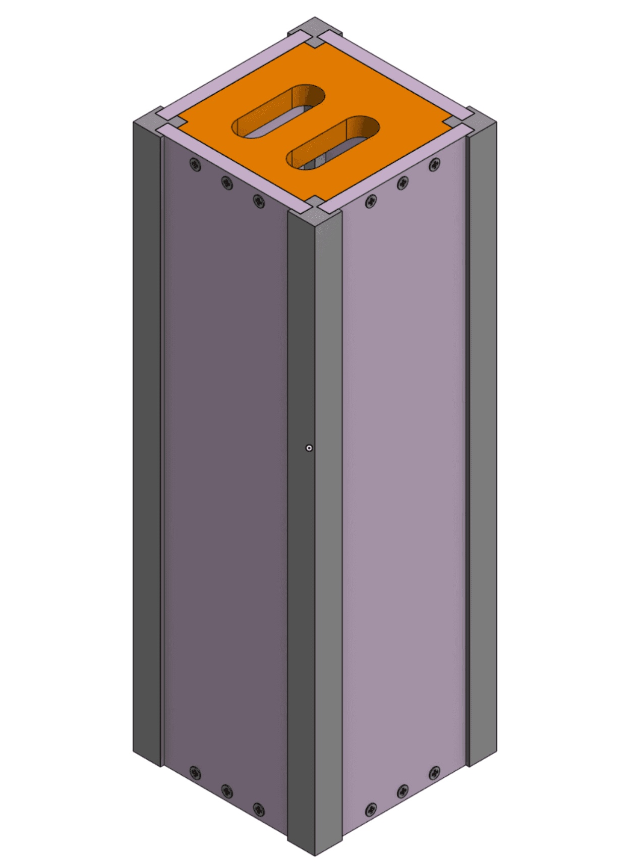
Design 2: This design serves as both the payload housing and retention system, hence its internal dimensions are configured to the 3U CubeSat format (100mm x 100mm x 300mm).
It encloses the payload with removable walls (in pink) that are screwed into the top/bottom end plates (in orange) and secured with aluminum rails (in dark grey).

Design 3: This design houses the payload within an aluminum cage that is secured with an aluminum retention plate and tensioning rods.
It also features aluminum tabs (in dark grey) to prevent horizontal motion in the payload.
Design 4: This design was derived from the previous cage system in Design 3. It features a retention plate that utilizes machined cutouts to constrain horizontal motion in the payload.
This design also integrates the retention subsystem with the rocket's upper bulkhead and ballast system (in dark grey), since the two tensioning rods are used to secure both the retention plate and ballast plates.
Design 1: This design secures the payload (in blue) with an aluminum retention plate, brackets, and tensioning rods.
It also features 3D printed PLA spacers (in orange) that fill the space between the payload and inner walls of the rocket's body tube, which provide protection from side impacts as well as limit horizontal vibrations.
Design 2: This design serves as both the payload housing and retention system, hence its internal dimensions are configured to the 3U CubeSat format (100mm x 100mm x 300mm).
It encloses the payload with removable walls (in pink) that are screwed into the top/bottom end plates (in orange) and secured with aluminum rails (in dark grey).
Design 3: This design houses the payload within an aluminum cage that is secured with an aluminum retention plate and tensioning rods.
It also features aluminum tabs (in dark grey) to prevent horizontal motion in the payload.
Design 4: This design was derived from the previous cage system in Design 3. It features a retention plate that utilizes machined cutouts to constrain horizontal motion in the payload.
This design also integrates the retention subsystem with the rocket's upper bulkhead and ballast system (in dark grey), since the two tensioning rods are used to secure both the retention plate and ballast plates.
Design 1: This design secures the payload (in blue) with an aluminum retention plate, brackets, and tensioning rods. It also features 3D printed PLA spacers (in orange) that fill the space between the payload and inner walls of the rocket's body tube, which provide protection from side impacts as well as limit horizontal vibrations.
Design 2: This design serves as both the payload housing and retention system, hence its internal dimensions are configured to the 3U CubeSat format (100mm x 100mm x 300mm). It encloses the payload with removable walls (in pink) that are screwed into the top/bottom end plates (in orange) and secured with aluminum rails (in dark grey).
Design 3: This design houses the payload within an aluminum cage that is secured with an aluminum retention plate and tensioning rods. It also features aluminum tabs (in dark grey) to prevent horizontal motion in the payload.
Design 4: This design was derived from the previous cage system in Design 3. It features a retention plate that utilizes machined cutouts to constrain horizontal motion in the payload. This design also integrates the retention subsystem with the rocket's upper bulkhead and ballast system (in dark grey), since the two tensioning rods are used to secure both the retention plate and ballast plates.
Design 4 was selected as the concept for further development as it offered the most potential to fulfil the previously mentioned design requirements.
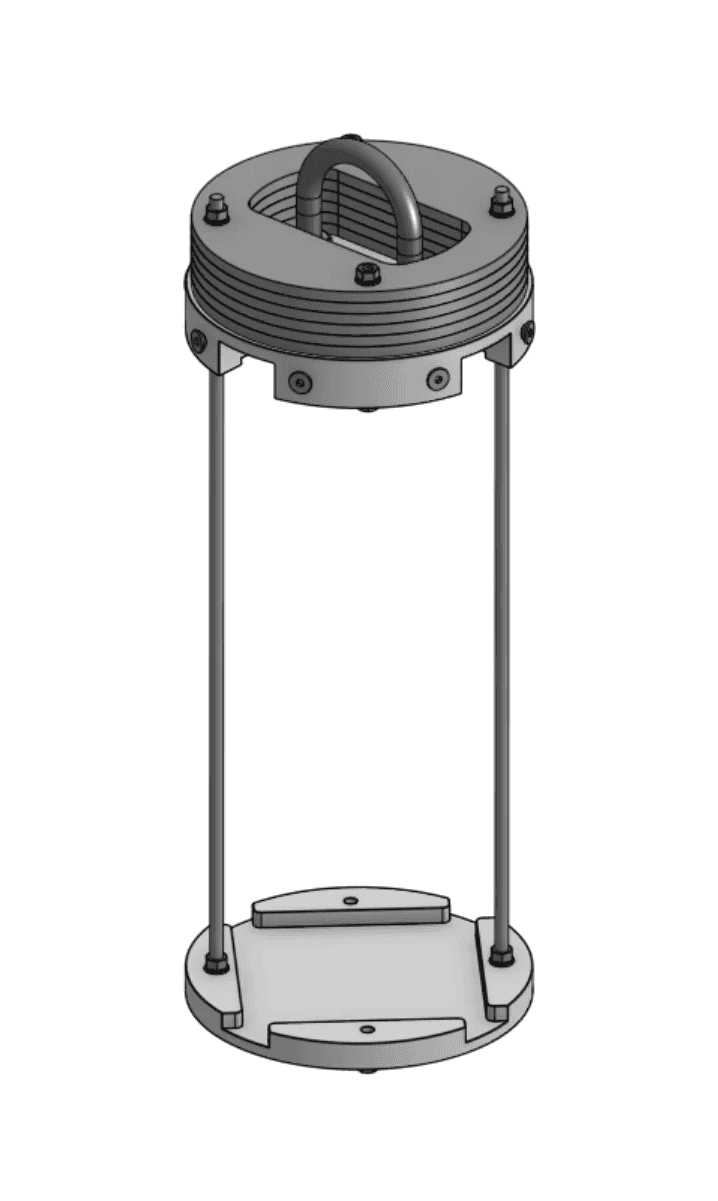
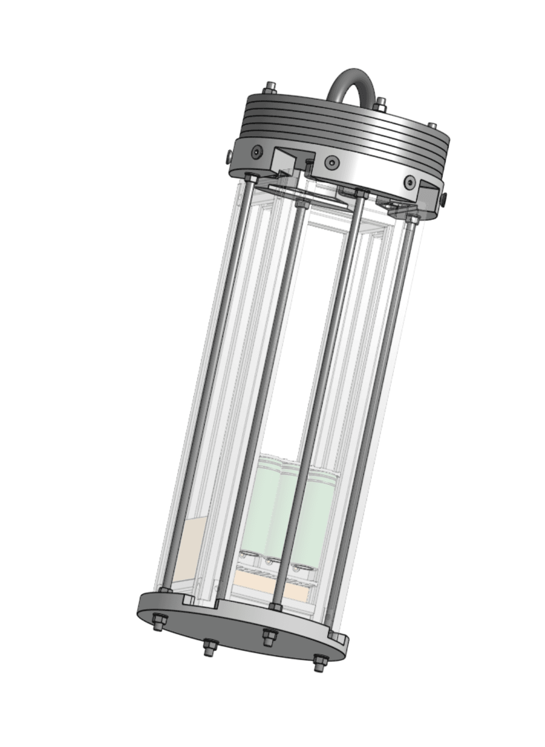
The initial design features a 10 mm thick aluminum retention plate that contains a 100mm x 100mm x 7mm recess. This recess allows the plate to securely attach to the base of a payload with 3U CubeSat dimensions (100mm x 100mm x 300mm) whilst both components are fastened to the upper bulkhead/ballast system by two 375 mm long M5 threaded steel rods (see image below).

CAD model of Design 4 with the payload housing tensioned against the upper bulkhead/ballast system, using threaded rods that are fastened to the retention plate.
finite element analysis
Finite element analysis was performed on the retention plate on SolidWorks to simulate the effects of the payload accelerating against it during launch and motor burning (see images below).
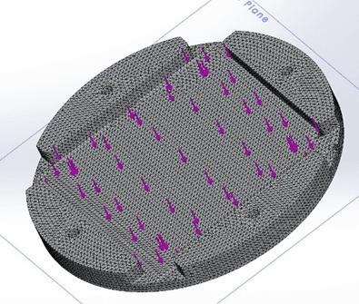
A distributed loading on the inner face of the retention plate's recess was used to simulate the payload pressing against the retention plate during launch.
Finer meshes were also set at the retention plate's rod holes for better observation of the stress sustained by the plate in these regions.
However, the results indicated that Design 4 failed to support a load of 1.5 times the expected maximum load, meaning that it did not achieve the minimum targeted safety factor of 1.5. This is seen in the image below, which illustrates the stress distribution across the retention plate during a simulated launch. The red regions indicate areas of the retention plate that would have deformed in a real launch, as the stress in these regions exceeded the yield strength of aluminum (the maximum stress that can be applied to aluminum before it begins to permanently deform).
However, the results indicated that Design 4 failed to support a load of 1.5 times the expected maximum load, meaning that it did not achieve the minimum targeted safety factor of 1.5.
This is seen in the image below, which illustrates the stress distribution across the retention plate during a simulated launch. The red regions indicate areas of the retention plate that would have deformed in a real launch, as the stress in these regions exceeded the yield strength of aluminum (the maximum stress that can be applied to aluminum before it begins to permanently deform).
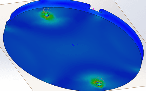
Distribution of stress along the underside of the retention plate in Design 4.
Design 4 was consequently revised to feature a new retention plate thickness of 12mm (the recess dimensions remained unchanged) alongside four threaded rods instead of two. This was intended to improve the design's load bearing performance and increase its safety factor.
The revised design was subjected again to finite element analysis and mass optimization studies to optimize the strength of the design while minimizing its mass. This culminated in a solution that fulfilled the load-bearing and mass requirements, where the design achieved an optimized retention plate mass of 115.61g, a total mass of 365g (1 retention plate and 4 threaded rods), alongside a safety factor of 2.
The revised payload retention after performing finite element analysis and mass optimization studies.
the final design
The finalized payload retention consists of an aluminum retention plate that fastens a payload of 3U CubeSat dimensions to the upper bulkhead/ballast system via four M5 threaded steel rods that are 375 mm long. The design weighs 365g in total and was determined with finite element analysis to have a safety factor of 2.
As shown below, this subsystem integrates into the rocket without interfering with the coupler subassembly below it (in light gray). The payload retention can be easily accessed from the coupler side, in which the payload can be inserted/removed by undoing the fastening nuts on the retention plate and removing the plate to access the cavity.
Thus, the final design of the payload retention subsystem fulfills all of its design requirements (see above).

The finalized payload retention in the rocket's upper body tube.
manufacturing
The manufacturing process for the payload retention's components was relatively simple; the retention plate was CNC machined from an Al-6061 aluminum block while the threaded steel rods were commercially sourced and cut to the specified length (375 mm).
All machined components in Florence were made by MCHND, an Adelaide-based manufacturer that sponsored the club's CNC machining projects. Since the retention plate was manufactured externally, I created an engineering drawing of the retention plate (see below) to communicate its specifications. This was my first time drafting an engineering drawing, and it was a great opportunity to learn about presenting a design according to engineering conventions.
The manufacturing process for the payload retention's components was relatively simple; the retention plate was CNC machined from an Al-6061 aluminum block while the threaded steel rods were commercially sourced and cut to the specified length (375 mm).
All machined components in Florence were made by MCHND, an Adelaide-based manufacturer that sponsored the club's CNC machining projects.
Since the retention plate was to be manufactured externally, I created an engineering drawing of the retention plate (see below) to communicate its specifications. This was my first time drafting an engineering drawing, and it was a great opportunity to learn about presenting a design according to engineering conventions.

technical report
As a competitor in the 2024 Spaceport America Cup, ARES submitted a 180-page technical report regarding the design, validation/testing, and manufacturing processes used to build Florence. I contributed to the report by authoring the section regarding the payload retention subsystem, which can be downloaded from the link below.
tap/drag/pinch the model to explore
tap the dots beside to view other models
project name
Payload Retention
date
Aug. 2023 - Jun. 2024
overview
As a student engineer in the University of Melbourne's rocketry team (ARES), I designed and manufactured the payload retention subsystem for Project Florence, a rocket built by the team to compete in the 2024 Spaceport America Cup.
background
As a student engineer in the University of Melbourne's rocketry club (ARES), I was responsible for designing and manufacturing the payload retention subsystem for Florence (pictured right), a rocket designed to compete in the 30,000 ft category of the 2024 Spaceport America Cup.
The payload retention subsystem is essentially a protective frame/housing in which the rocket's payload (i.e. the rocket's cargo) stored.
It ensures that the payload does not wobble, vibrate, or become dislodged throughout the rocket's entire flight, especially during high acceleration events (launch, ascent, etc.)
Project Florence, 09/06/2024
design requirements
Designing the payload retention during Project Florence involved satisfying performance requirements and constraints stipulated by the rocket's design as well as the Spaceport America Cup rules. The payload retention's design requirements included the following:
The system should accommodate a payload with the dimensions of a 3U CubeSat (100mm x 100mm x 300mm).
The system must safely retain the payload in the rocket throughout the entire flight, especially during high acceleration conditions such as the launch and motor-burning flight sequences.
It must withstand the expected maximum load (902N) with a safety factor of 1.5-2 (i.e. be robust enough to support 1.5-2 times the expected maximum load).
The system should allow for convenient payload insertion/removal and be easily integrated within the rocket without interfering with neighboring subsystems.
The system's mass does not exceed 400g.
design iterations
Various designs were investigated for the payload retention subsystem, in which retention methods involving spacers, tensioning rods, cages, and removable walls were each investigated and evaluated. Here are some of the solutions that were explored:
Design 1: This design secures the payload (in blue) with an aluminum retention plate, brackets, and tensioning rods.
It also features 3D printed PLA spacers (in orange) that fill the space between the payload and inner walls of the rocket's body tube, which provide protection from side impacts as well as limit horizontal vibrations.
Design 2: This design serves as both the payload housing and retention system, hence its internal dimensions are configured to the 3U CubeSat format (100mm x 100mm x 300mm).
It encloses the payload with removable walls (in pink) that are screwed into the top/bottom end plates (in orange) and secured with aluminum rails (in dark grey).
Design 3: This design houses the payload within an aluminum cage that is secured with an aluminum retention plate and tensioning rods.
It also features aluminum tabs (in dark grey) to prevent horizontal motion in the payload.
Design 4: This design was derived from the previous cage system in Design 3. It features a retention plate that utilizes machined cutouts to constrain horizontal motion in the payload.
This design also integrates the retention subsystem with the rocket's upper bulkhead and ballast system (in dark grey), since the two tensioning rods are used to secure both the retention plate and ballast plates.
Design 1: This design secures the payload (in blue) with an aluminum retention plate, brackets, and tensioning rods. It also features 3D printed PLA spacers (in orange) that fill the space between the payload and inner walls of the rocket's body tube, which provide protection from side impacts as well as limit horizontal vibrations.
Design 2: This design serves as both the payload housing and retention system, hence its internal dimensions are configured to the 3U CubeSat format (100mm x 100mm x 300mm). It encloses the payload with removable walls (in pink) that are screwed into the top/bottom end plates (in orange) and secured with aluminum rails (in dark grey).
Design 3: This design houses the payload within an aluminum cage that is secured with an aluminum retention plate and tensioning rods. It also features aluminum tabs (in dark grey) to prevent horizontal motion in the payload.
Design 4: This design was derived from the previous cage system in Design 3. It features a retention plate that utilizes machined cutouts to constrain horizontal motion in the payload. This design also integrates the retention subsystem with the rocket's upper bulkhead and ballast system (in dark grey), since the two tensioning rods are used to secure both the retention plate and ballast plates.
Design 4 was selected as the concept for further development as it offered the most potential to fulfil the previously mentioned design requirements.
The initial design features a 10 mm thick aluminum retention plate that contains a 100mm x 100mm x 7mm recess. This recess allows the plate to securely attach to the base of a payload with 3U CubeSat dimensions (100mm x 100mm x 300mm) whilst both components are fastened to the upper bulkhead/ballast system by two 375 mm long M5 threaded steel rods (see image below).
CAD model of Design 4 with the payload housing tensioned against the upper bulkhead/ballast system, using threaded rods that are fastened to the retention plate.
finite element analysis
Finite element analysis was performed on the retention plate on SolidWorks to simulate the effects of the payload accelerating against it during launch and motor burning (see images below).
A distributed loading on the inner face of the retention plate's recess was used to simulate the payload pressing against the retention plate during launch.
Finer meshes were also set at the retention plate's rod holes for better observation of the stress sustained by the plate in these regions.
However, the results indicated that Design 4 failed to support a load of 1.5 times the expected maximum load, meaning that it did not achieve the minimum targeted safety factor of 1.5.
This is seen in the image below, which illustrates the stress distribution across the retention plate during a simulated launch.
The red regions indicate areas of the retention plate that would have deformed in a real launch, as the stress in these regions exceeded the yield strength of aluminum (the maximum stress that can be applied to aluminum before it begins to permanently deform).
Distribution of stress along the underside of the retention plate in Design 4.
Design 4 was consequently revised to feature a new retention plate thickness of 12mm (the recess dimensions remained unchanged) alongside four threaded rods instead of two. This was intended to improve the design's load bearing performance and increase its safety factor.
The revised design was subjected again to finite element analysis and mass optimization studies to optimize the strength of the design while minimizing its mass.
This culminated in a solution that fulfilled the load-bearing and mass requirements, where the design achieved an optimized retention plate mass of 115.61g, a total mass of 365g (1 retention plate and 4 threaded rods), alongside a safety factor of 2.
The revised payload retention after performing finite element analysis and mass optimization studies.
the final design
The finalized payload retention consists of an aluminum retention plate that fastens a payload of 3U CubeSat dimensions to the upper bulkhead/ballast system via four M5 threaded steel rods that are 375 mm long. The design weighs 365g in total and was determined with finite element analysis to have a safety factor of 2.
As shown below, this subsystem integrates into the rocket without interfering with the coupler subassembly below it (in light gray).
The payload retention can be easily accessed from the coupler side, in which the payload can be inserted/removed by undoing the fastening nuts on the retention plate and removing the plate to access the cavity.
Thus, the final design of the payload retention subsystem fulfills all of its design requirements (see above).
The finalized payload retention in the rocket's upper body tube.
manufacturing
The manufacturing process for the payload retention's components was relatively simple; the retention plate was CNC machined from an Al-6061 aluminum block while the threaded steel rods were commercially sourced and cut to the specified length (375 mm).
All machined components in Florence were made by MCHND, an Adelaide-based manufacturer that sponsored the club's CNC machining projects.
Since the retention plate was manufactured externally, I created an engineering drawing of the retention plate (see below) to communicate its specifications.
This was my first time drafting an engineering drawing, and it was a great opportunity to learn about presenting a design according to engineering conventions.
technical report
As a competitor in the 2024 Spaceport America Cup, ARES submitted a 180-page technical report regarding the design, validation/testing, and manufacturing processes used to build Florence. I contributed to the report by authoring the section regarding the payload retention subsystem, which can be downloaded from the link below.